-
English
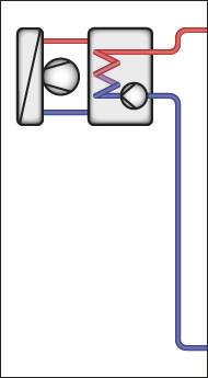
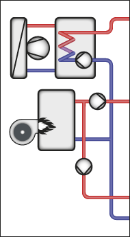
Please choose your system configuration from the menu at the top or enter your SD-Number directly below.


| 17 | temp.sensor | N | 16 | ||||
| HC1 flow temperature | 18 | temp.sensor | L | 15 | |||
| 19 | temp.sensor | potential for 13 | 14 | ||||
| 20 | temp.sensor | relay output | 13 | Group fault message | |||
| 21 | temp.sensor | not used | 12 | ||||
| Buffer tank temperature Heat Pump / Strategy | 22 | temp.sensor | relay output | 11 | HC1 valve CLOSE | ||
| 23 | temp.sensor | potential for 9+11 | 10 | ||||
| 24 | temp.sensor | relay output | 9 | HC1 valve OPEN | |||
| 25 | counter/contact | not used | 8 | ||||
| 26 | counter/contact | relay output | 7 | HC1 pump | |||
| 27 | 0..10V | potential for 5+7 | 6 | ||||
| 28 | 0..10V | relay output | 5 | ||||
| 29 | ground for 17-28 | not used | 4 | ||||
| 30 | not used | relay output | 3 | ||||
| 31 | not used | potential for 1+3 | 2 | ||||
| 32 | not used | relay output | 1 |
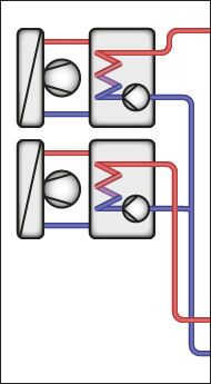
For the 2nd HP is needed an additional HPM + INT-x cable, in which SD-No. 80000 must be loaded.
For the connection between the HPM controllers (master/slave), an ethernet-switch and network-cables are required.
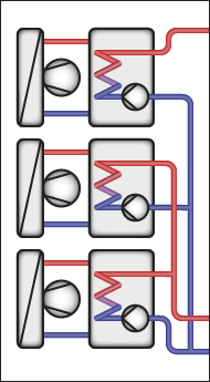
For the 2nd HP is needed an additional HPM + INT-x cable, in which SD-No. 80000 must be loaded.
For the 3rd HP is needed an additional HPM + INT-x cable, in which SD-No. 90000 must be loaded.
For the connection between the HPM controllers (master/slave), an ethernet-switch and network-cables are required.